Everyone knows the PS2, right? Well okay, not EVERYONE, but a good majority of those who are reading this article I bet. The PlayStation 2, continued from the PlayStation and launched by Sony in… wait. I’m not wikipedia am I? Just browse there if you want the usual info.
So what I’m going to talk about today is how the PS2 itself was designed and how it is used by developers with both smart and un-smart tricks.
Introduction to PS2 Hardware
One of the first things to know about the PS2 is that it has two main MIPS CPUs. Those are the MIPS R5900 and MIPS R3000. Why two, you may ask? Well simply because of its name. It is the PlayStation TWO, which means a PlayStation ONE existed before and so retro-compatibility was born. Another thing to consider before diving a bit into the software is that EVERYTHING in the PlayStation 2 is a CPU. Seriously. You have the two main CPUs, the IO Processor, two Sound Processing Units, the GPU, Graphics Synthetizer (GS), the main PS2 CPU (dubbed Emotion Engine, which contains the Image Processing Unit), two Vector Processing Units (think of them like shader processors), two Integer Units, a Floating-Point Unit coprocessor (dubbed COP1), an additional Memory Unit called ScratchPad (SPR) for quick transfer, ten very efficient DMA Channels, the usual Memory Management Unit et cetera.
For the sake of completeness, COP0 is basically the rest of the EE including MMU, DMA, and so on. COP2 is the VU0Macro interface. We’ll call VPU cores VUs in that article.
With that out of the way, your first thougt might be that this is insane (or if you’re like me, awesome) and you’d be right! In either case, it’s a treasure when it comes to over-engineering!
Then comes back the logic to haunt us; it’s great and all to have all of those CPUs, but how can you make them interact quickly and in an usable fashion?
And to that I’d responde, “A picture is worth a thousand words.”
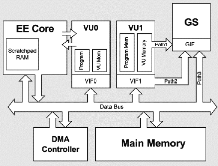
Simplified PS2 interaction diagram
Hardware interconnections and rendering paths
The first thing that every developer noticed about the PS2 is how different it was from other systems: it was not tailored to a specific use, unlike the GameBoy, yet design choices were radically different from modular devices such as the PC, having tons of sub blocks as opposed to a simple computer where you generally have a CPU and GPU and that’s it in its higher view.
That’s where most of the mainstream views of “complexity” and the famous cluster of PS2 arranged as a supercalculator born into existence. Indeed this console had pretty good potential, but this lead to another issue: normal developers never worked on such a non-sequential system that worked in the game dev world!
That’s where rendering paths come into play.
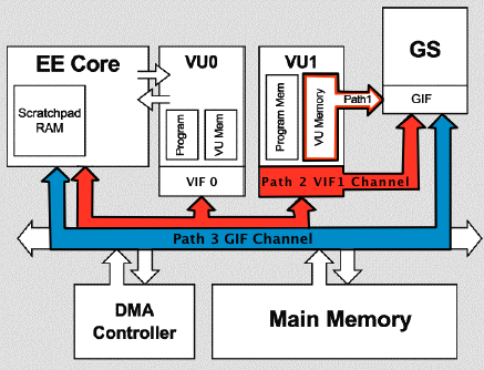
PS2 rendering paths
This was the worst mistake you could’ve done.
If you look at the rendering paths, you’ll notice something. It seems like Path Three
rendering is the most direct and efficient way to get the task done.
So you might think that this is good enough.
This is forgetting that you are working on the PS2.
The main CPU of the PS2 (EE) is clocked at 294.912 MHz.
Let’s now check Xbox CPU frequency: 733MHz.
Is the Xbox really that good? Well no, you are just a bad developer. =)
While it may sound more direct, you’ll face the issue of having an overloaded
CPU. It’s already doing all the main logic and are trying to send MORE data at an
insane rate to the GPU, since its Graphics Interchange Interface have only 4MB
of RAM available for you.
Then how can we go about this without overloading anything?
That’s what you’ve missed on the SDK by skipping some files.
It is called “Path Two Rendering”.
Not-so-quick travel through the world of software development
So now that we have a general idea of hardware and ways to use it, let’s stop a bit on the side of PlayStation 2 software. Other than the beautiful ELF referred as 32 bits instead of 64 and wrong CPU model leading to beautiful hacks for reverse engineering toolkits, the PS2 has its own set of oddities from more “standard” development.
As the Path Two rendering is the most common for demanding tasks on this console,
I will go on and present it.
Let us visualize an example to understand it.
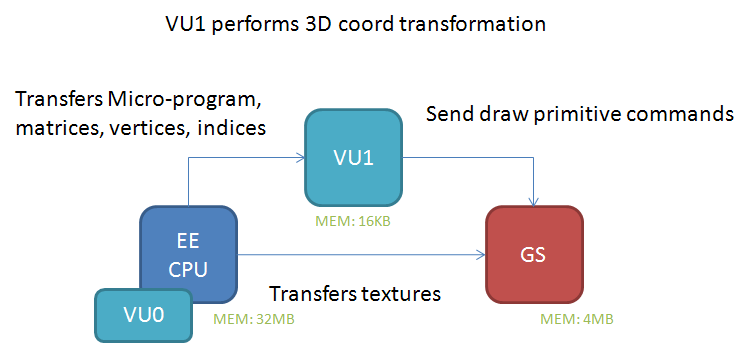
Path Two Example
In a nutshell, we have the main CPU doing the core logic of the game that sends your compiled model data, or about anything that needs processing power, to the VU1, then feeding it to the GS through the VIF interface while the EE core is feeding texture data to the GS asynchronously. Now that we understand that, here comes another reason the first PS2 games had so much trouble being consistent: VU1 core main programming language is… a custom assembly language. Yup. While a VU preprocessor got released a pretty long time after initial release of the PS2 SDK and that we now have an open source implementation of it, it still is something vastly unused in homebrew.
So now we figured out how to make use of the other CPU, but we are still facing
another issue: how can we fit bigger models in the VU1 RAM of 16kb?
Well, to see how that is done in professional games my friend, let us look at the
internal logic of the PlayStation 2 game, “Kingdom Hearts 2”.
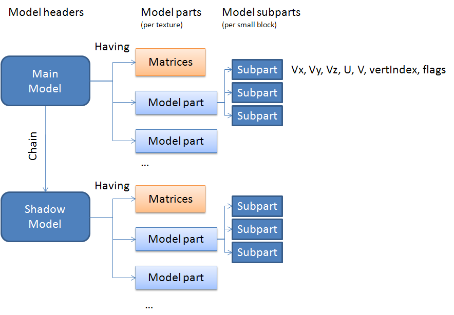
Sliced Models
Yup, we actually slice bigger models in model parts! While this may not be the
only reason it was implemented in said game (changing shaders per model part),
it still is a big enough reason to implement it!
Another limitation of this cache limit is that we have to abuse the bandwitdth to
get an actual usable result. VU and GS cache aren’t big enough to always store
all models, so you have to stream them in realtime. Although that may seem pretty
agressive for the console, knowing its cache limit, its bandwidth is actually
pretty amazing for the time and this surprisingly wasn’t an issue.
So let’s try to get back a somewhat understandable summary of all of this: You have the EE, which sends the 3D data to be processed into the VU1 core, which itself kicks the data into the GS instead of procedurally kicking everything into the GS, and then process the conversions into the main CPU. That basically means that every 3D model in the current setup is a compiled shader, all modified at runtime!
Here is an example implementation to clear up ideas about how it is done.
First the main logic done by the EE core (Test_PS2_VU1Triangle is assumed to be called):
void Test_PS2_VU1Triangle(void)
{
    [...]

    VIFDMA_Initialize(&vif_dynamic_dma, /* pages = */ 8, VIF_DYNAMIC_DMA);
    VIFDMA_Initialize(&vif_static_dma,  /* pages = */ 8, VIF_STATIC_DMA);

    // VU1Prog_Color_Triangles is what actually handles the vertices data sent
    //to VU1 memory using DrawVU1Triangle
    VU_ProgManagerInit(&vu_prog_mgr);
    VU_InitMicroprogram(&vif_static_dma, &VU1Prog_Color_Triangles, VU1_MICROPROGRAM, /* offset = */ 0);
    VU_UploadMicroprogram(&vu_prog_mgr, &vif_dynamic_dma, &VU1Prog_Color_Triangles,  /* index  = */ 0, /* force = */ true);
    VIFDMA_Fire(&vif_dynamic_dma);

    [...]

    for (;;)
    {
        PS2_BeginFrame(0);


        Mat4_MakeRotationZ(&rotation_matrix, rotation_angle);
        Mat4_MakeTranslation(&translation_matrix, 1.0f, 0.0f, 0.0f);
        Mat4_Multiply(&model_matrix, &rotation_matrix, &translation_matrix);
        Mat4_Multiply(&mvp_matrix, &model_matrix, &view_proj_matrix);

        DrawVU1Triangle(&dd, &mvp_matrix);

        rotation_angle += 0.02f;
        PS2_EndFrame();
    }
}

static void DrawVU1Triangle(draw_data_t * dd, const m_mat4_t * mvp)
{
    DrawDataReset(dd);
    DrawDataAddMatrix(dd, mvp);
    DrawDataAddScaleFactorsAndVertCount(dd, 3); // 1 triangle = 3 verts

    VU1_Begin();

    // Matrix/scales will be uploaded at address 0 in VU memory.
    const int draw_data_qwsize = DrawDataGetQWordSize(dd);
    VU1_ListData(0, dd->buffer, draw_data_qwsize);

    // Data added from here will begin at address 6, right after the MVP, fScales and vert count:
    VU1_ListAddBegin(draw_data_qwsize);

    // The GIF Tag and primitive description:
    const int vert_loops = CountVertexLoops(/* vertex_qwords = */ 6, NUM_VERTEX_ELEMENTS);
    const u64 prim_info  = GS_PRIM(GS_PRIM_TRIANGLE, GS_PRIM_SFLAT, GS_PRIM_TOFF, GS_PRIM_FOFF, GS_PRIM_ABOFF, GS_PRIM_AAON, GS_PRIM_FSTQ, GS_PRIM_C1, 0);
    const u64 gif_tag    = GS_GIFTAG(vert_loops, 1, 1, prim_info, GS_GIFTAG_PACKED, NUM_VERTEX_ELEMENTS);
    VU1_ListAdd128(gif_tag, VERTEX_FORMAT);

    //WARNING: Data here could also be sent as an asset loaded dynamically from
    //the game, this is just a glorified way of hardcoding assets.
    //
    // Vertex format:
    // Color (RGBA bytes)
    // Position (X,Y,Z,W floats)
    //

    // Vertex 0:
    VU1_ListAdd32(50);
    VU1_ListAdd32(50);
    VU1_ListAdd32(127);
    VU1_ListAdd32(127);
    VU1_ListAddFloat(-1.0f);
    VU1_ListAddFloat(1.0f);
    VU1_ListAddFloat(3.0f);
    VU1_ListAddFloat(1.0f);

    // Vertex 1:
    VU1_ListAdd32(50);
    VU1_ListAdd32(50);
    VU1_ListAdd32(127);
    VU1_ListAdd32(127);
    VU1_ListAddFloat(-1.0f);
    VU1_ListAddFloat(-1.0f);
    VU1_ListAddFloat(3.0f);
    VU1_ListAddFloat(1.0f);

    // Vertex 2:
    VU1_ListAdd32(50);
    VU1_ListAdd32(50);
    VU1_ListAdd32(127);
    VU1_ListAdd32(127);
    VU1_ListAddFloat(0.5f);
    VU1_ListAddFloat(0.5f);
    VU1_ListAddFloat(3.0f);
    VU1_ListAddFloat(1.0f);

    // 13 qwords total so far (verts + matrix/scales draw data)
    VU1_ListAddEnd();

    // End the list and start the VU program (located in micromem address 0)
    VU1_End(0);
}
And here is the microprogram the VU1 core is actually running to render the vertices data, shown under the name of “VU1Prog_Color_Triangles” in the EE logic:
; Data offsets in the VU memory (quadword units):
#define kMVPMatrix    0
#define kScaleFactors 4
#define kVertexCount  4
#define kGIFTag       5
#define kStartColor   6
#define kStartVert    7

#vuprog VU1Prog_Color_Triangles

    ; Clear the clip flag so we can use the CLIP instruction below:
    fcset 0

    ; Number of vertexes we need to process here:
    ; (W component of the quadword used by the scale factors)
    ilw.w iNumVerts, kVertexCount(vi00)

    ; Loop counter / vertex ptr:
    iaddiu iVert,    vi00, 0 ; Start vertex counter
    iaddiu iVertPtr, vi00, 0 ; Point to the first vertex (0=color-qword, 1=position-qword)

    ; Rasterizer scaling factors:
    lq fScales, kScaleFactors(vi00)

    ; Model View Projection matrix:
    MatrixLoad{ fMVPMatrix, kMVPMatrix, vi00 }

    ; Loop for each vertex in the batch:
    lVertexLoop:
        ; Load the vert (currently in object space and floating point format):
        lq fVert, kStartVert(iVertPtr)

        ; Transform the vertex by the MVP matrix:
        MatrixMultiplyVert{ fVert, fMVPMatrix, fVert }

        ; Clipping for the triangle being processed:
        clipw.xyz fVert, fVert
        fcand     vi01,  0x3FFFF
        iaddiu    iADC,  vi01, 0x7FFF

        ; Divide by W (perspective divide):
        div     q,     vf00[w], fVert[w]
        mul.xyz fVert, fVert,   q

        ; Apply scaling and convert to FP:
        VertToGSFormat{ fVert, fScales }

        ; Store:
        sq.xyz fVert, kStartVert(iVertPtr) ; Write the vertex back to VU memory
        isw.w  iADC,  kStartVert(iVertPtr) ; Write the ADC bit back to memory to clip the vert if outside the screen

        ; Increment the vertex counter and pointer and jump back to lVertexLoop if not done.
        iaddiu iVert,    iVert,     1 ; One vertex done
        iaddiu iVertPtr, iVertPtr,  2 ; Advance 2 Quadwords (color+position) per vertex
        ibne   iVert,    iNumVerts, lVertexLoop
    ; END lVertexLoop

    iaddiu iGIFTag, vi00, kGIFTag ; Load the position of the GIF tag
    xgkick iGIFTag                ; and tell the VU to send that to the GS

#endvuprog
To close this wall of code I’ll just summarize what it does and try to make it somewhat understandable:
- We initialize DMA interface to the VU1 core (known as “VIF”),
- We upload our microcode to process the triangle data,
- We enter an infinite loop which will increment a rotation value each frame,
- We modify our custom compiled shader format (let’s call it that) with rotation values at runtime,
- We shoot this over to the VU1 core,
- Our microcode process the data and sends back the primitives to draw to the GS,
- Then we go back to the beginning of our infinite loop.
Before moving on, here’s a little takeaway: while texture mapping isn’t defined here nor shown, it is fully possible to do and is generally done! This method of calculation also allows for shaders and pretty much anything, so don’t think of it as a tailored down version of an OpenGL shader processor!
Back to the world of Paths rendering
Well that was confusing. Now that we’ve covered most of Path Two and Three
rendering, the logic followup would be to cover Path One rendering, right?
Well, it isn’t as simple as it sounds because… as a matter of fact, we already
used it!
Path One rendering, if you remember the diagram shown a while ago, is actually
a simple transfer from VU1 memory to the GS, and isn’t that what we technically
do during Path Two rendering? Okay I admit we do actual calculations on the VU1
core and do not transfer directly to the GS memory, but this still qualifies
as Path One rendering as far as I’m aware!
And now that we’re talking, we also used Path Three rendering while sending up
the texture data, so indeed, the PS2 actually asynchronusly used three different
rendering technics to show up on your screen. Pretty amazing, right?
As a sidenote, if you would like to know more about GIF and texture swizzling
used by the GS internal texture format, you should read this
paper and check its
implementation.
And now comes the biggest part of this diagram, which I avoided: what about VU0?
Well let’s think of it this way: where is VU0 located and what does it do generally?
The answer to this (rhetorical) question is of course the EE core,
which is doing main game logic. So VU0 is basically done for anything else that
could be sped up but cannot be done by the VU1 core. This could be
ray-tracing/physics, animation using keyframe calculation, pre-processing of a
non-streamed music format or even 3D rendering (Again!). Although from my own
experience, VU0 is generally more unused than VU1; it is used basically as an
alternate core that does a bit of everything. The thing to note, though, is that
it has two modes compared to VU1 (micro and macro) and is generally used through
macro under the COP2 interface, allowing for quicker calculations than VU1 but
leading it to a more limited subset of operation available in its ISA.
While I was unable to give you a complete exhaustive list of all cores and their uses for the PS2 (I’m thinking especially about the SPU-2, IOP, and others here), I hope I’ve given you a good enough overview of the rendering pipeline of the PlayStation 2 and how much a different implementation can completely change your experience with a device!
Conclusion
The PS2 is a subject I’ve wanted to tackle for awhile, as I’ve been working on it for now quite some time. Hell, if I had the time I could even write my own emulator for it! This was a pretty amazing piece to tackle as it’s basically the polar opposite of the other competing platforms back in the day. A lot of non-sequential parallel cores doing calculations, very little cache and fricking insane bandwidth. It really shows how much a different system can matter in the devlopment world!
This was also the first article of “Implementation Matters”, a series I hope to
make about weird machines that have to be used in a certain way to show their
true potential! Can’t promise to make a sequel though.
If you have anything you’d like to add, think I should correct, or just think I’m
stupid and am not worthy of talking on the internet, please feel free to contact me
on twitter, through mail, or anything really!
Resources
I’d like to thank Guilherme Lampert for his codebase of a Quake 2 port from which the example VU1 microcode is taken (And as one of the only homebrew PS2 devs that have figured out VU1 microprogramming, congrats!), Robin Green at Gamasutra for the original illustrations I’ve used as a simplified PS2 diagram, the ps2sdk team that is somehow still around, and everyone else I’ve forgotten! The PS2 homebrew scene has always been lacking due to the complexity of the hardware and it’s always been fun to think about it, so I hope you had a good time reading this too!